
AstroSDR
Description
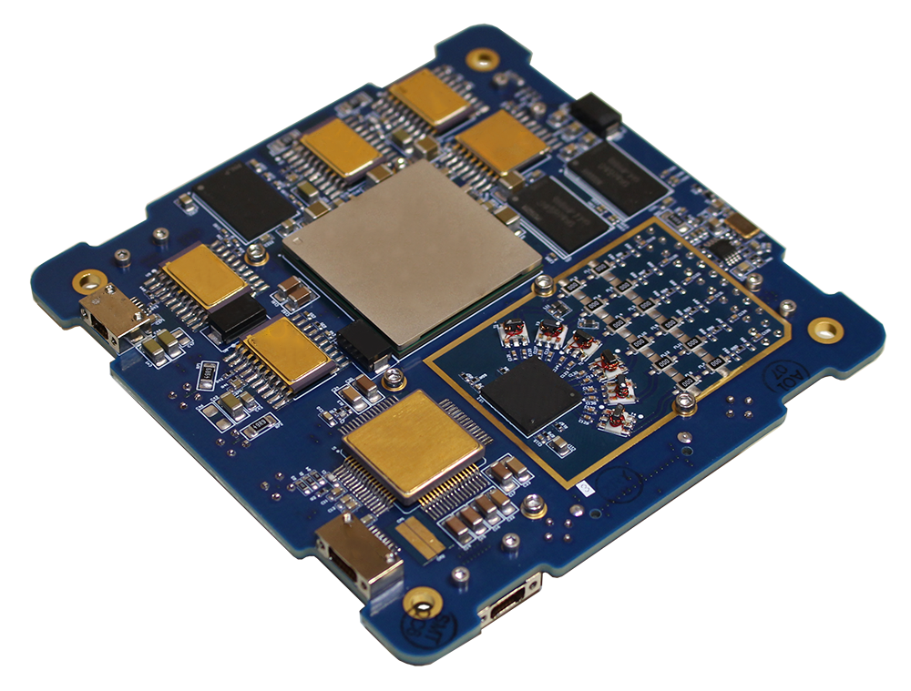
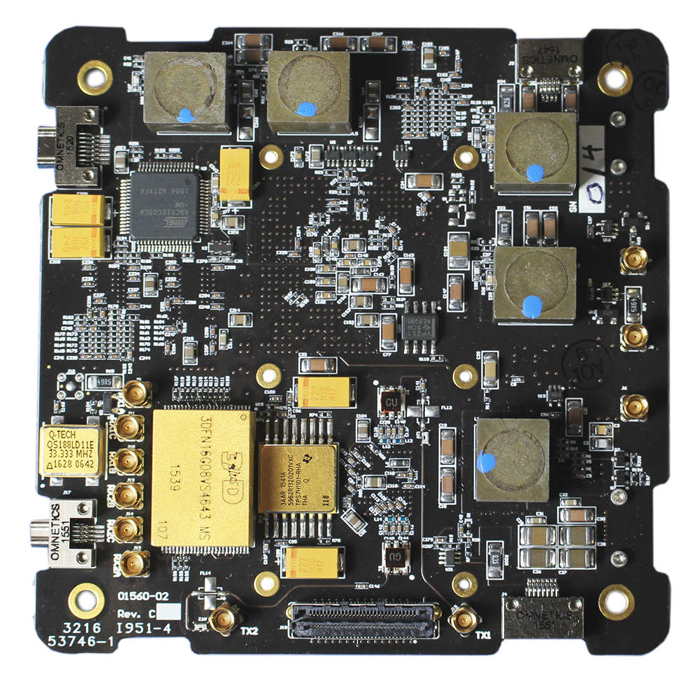
Rincon Research Corporations’s AstroSDR product family provides key components for a user-developed RF payload: receiver, transmitter, FPGA, ARM processor, data storage, and high-speed I/O. The board-support-package includes pre-built functions for interfacing to the radio, ARM processor, and eMMC storage, as well as Vivado project to assist the user in developing their own unique applications.
AstroSDR has the developer-friendly features found in our terrestrial SDR and DSP systems. The on-board processor runs embedded Linux, providing a flexible and capable development environment. APIs are provided for basic control of the FPGA, receivers, and transmitters.
AstroSDR has multiple interfaces for I/O and command/control: dual UARTS, two FPGA-attached LVDS pairs, and an Ethernet interface on an optional daughter-card.
Rincon Research Corporation supports missions with more than just hardware. We provide mission planning and operation services. We also have unique IP for digital signal processing, including interference cancelation, high-rate modems, adaptive beamforming, geolocation, and space situational awareness.
For information about AstroSDR flight, see the AstroSDR Space Flight page.
Features
- Dual receivers & transmitters, 70 MHz to 6 GHz
- Zynq 7045 FPGA & processor system-on-chip (SoC)
- Daughter-card interface for expansion, I/O, and custom applications
- 64 GByte eMMC flash memory card
- Gigabit Ethernet and flash memory card with GPIO
- 64 GByte eMMC flash for data storage (optional daughter card)
Documentation
Order
Orderable Part Numbers:
ASDR-RF-S-00
ASDR-RF-E-00
ASDR-RF-CGF-00
ASDR-DC-GE32G-01–Gigabit Ethernet and Flash Memory Daughter Card
ASDR-DC-64G-01–Flash Memory Daughter Card
- m = Model (S, E, or CGF)
- S = Flight model
- E = Engineering model
- CGF = Commercial model
- c = Customization Code
- 00 = Standard
- 01 = Optional
AstroSDR has a flexible RF path, permitting installation of mission-specific filters at time of order. Contact us to develop a custom variant for your mission’s RF requirements.
ECCN is 9A515.x.
Orders may be placed via e-mail, telephone, fax, or mail.
Commercial Price List available upon request.
E-mail: sales@rincon.com
Phone: 520-519-3131
Fax: 520-519-3120
Mail: Rincon Research Corporation
Attention: Sales
101 North Wilmot Road, Suite 101
Tucson, AZ 85711
WARNING: Commodities, including associated software, firmware, and technical data, offered for sale on this site are controlled for export by the U.S. Department of State under the International Traffic in Arms Regulations (ITAR) or by the Department of Commerce under the Export Administration Regulations (EAR). Purchaser is required by U.S. law to comply with these regulations. Export, re-export, and retransfer of these commodities by any means without the required licenses or other U.S. Government authorization is prohibited by U.S. law.
Technical Specifications
System-on-Chip
ARM Zynq 7045 FPGA and dual ARM SoC
Processor: Dual-core ARM Cortex A9 with NEON, up to 733 MHz
Memory: 512 Mbyte DDR3 RAM (w/ECC)
Storage: 2 GByte Flash for radiation-tolerant OS storage
FPGA
350k logic cells, 900 DSP slices
Attached Memory: 1 GByte DDR3 RAM (ECC capable)
Attached Storage: 64 GByte eMMC flash on optional daughter card designed to support up to 8 MS/s (32 Mbytes/s)
Each eMMC supports sustained write speeds of 8Ms/s
Tuning Range
RX and TX: 70 MHz to 6 GHz
Dual RX (single RX LO) / Dual TX (single TX LO)
3 input paths per RX / 1 path per TX
Locations for SMT filters and matching networks on all RF paths
ADC/DAC Resolution
12 bit
Max Bandwidth
56 MHz single, 25 MHz dual (61.44 MSPS, 30.72 MSPS)
Timing Signals
FPGA connected, MMCX 50 Ohm connectors
1 PPS (2.0 V to 5.0 V)
IRIG-B-DC serial timecode (2.0 V to 5.0 V)
5/10/50 MHz reference (0.1 Vpp to 3.3 Vpp, -16 dBm to 14 dBm, sine wave or square wave)
Daughter Card Interface
30 pins 1.8 V GPIO (includes 11 ADC channels), 24 pins 3.3 V
GPIO.
(Samtec LSHM-130 60-pin strip available for
connections to custom board or cables)
LVDS
FPGA connected, 4 LVDS pairs, up to 200 MHz operation
9-pin nano-D connector
Supports HDLC (transmit only)
Supports SpaceWire link layer
Development Interface
External Watch Dog Timer Input, Reset, JTAG, UART console.
15-pin nano-D connector
Operating Temperature
–25°C to 60°C (flight)
0°C to 60°C (engineering and commercial — wider range available upon request)
Vibration Test
Passed GEVS proto-qualification levels
Thermal Vacuum Test
Passed CNGB spec –20°C to +50°C operational
Radiation
5+ years of on-orbit heritage, more info available upon request
Power
12 VDC
System Management
3.5 W (no FPGA load, ARM booted)
Idle
4 W (typ)
Passive Collect
5.5 W (typ - includes recording to flash)
Max
30 W
Dimensions
90 mm x 90 mm (3.543” x 3.543”)
Mass
Approximately 95 grams (without heatsink or optional daughter card) (90 grams for commercial model)